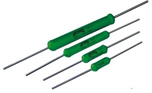
“SURE” BRAND WIRE WOUND RESISTOR - SSA SERIES
SILICON COATED AXIAL LEAD TYPE - Professional Grade
Features:
“SURE” BRAND WIRE WOUND RESISTOR - SSA SERIES
SILICON COATED AXIAL LEAD TYPE - Professional Grade
Features:
General Specifications:
DESCRIPTION
SSA
01
SSA
02
SSA
2.5
SSA
04
SSA
06
SSA
09
SSA
12
SSA
15
SSA
20
Resistance (1) range , Series
And tolerance (2)
± 10 %
± 5 %
E24 Series
0.01 Ω - 0.05 Ω
0.06 Ω - 100 KΩ
Rated dissipation at T amb = 70 °C
1 W
2 W
2.5 W
4 W
6 W
9 W
12 W
15 W
20 W
Temperature coefficient. (3)
R < 10 Ω: 0 to +600ppm/°C
R ≥ 10Ω: - 80 to +140ppm/°C
Operating temperature
- 40 °C to + 200 °C
Basic specification
IEC60 115-1
Limiting voltage
√ (Pn × R)
Stability D R/Rmax after:
Load
Climate tests
Resistance to soldering heat
Short time overload
± 5.0% + 0.1Ω
± 1.0% + 0.05Ω
± 0.5% + 0.05Ω
±2.0% + 0.1Ω
(1) Special resistive values available on request
(2) Tolerances, 0.5, 1, 3 and 10% available on request
(3) Temperature coefficient, 30, 50 and 90ppm/°C, available on request
Mechanical Data:
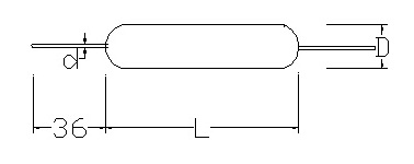
Table 1. Mechanical data
PRODUCT
L
D
d
SSA01
12.0 ± 1.5
4.5 ± 0.5
0.80 ± 0.03
SSA02
14.0 ± 1.5
5.5 ± 0.5
0.80 ± 0.03
SSA2.5
16.0 ± 1.5
5.5 ± 0.5
0.80 ± 0.03
SSA04
18.0 ± 1.5
6.5 ± 0.5
0.80 ± 0.03
SSA06
26.0 ± 1.5
7.5 ± 0.5
0.80 ± 0.03
SSA09
34.0 ± 1.5
8.5 ± 0.5
0.80 ± 0.03
SSA12
54.0 ± 1.5
7.5 ± 0.5
0.80 ± 0.03
SSA15
54.0 ± 1.5
8.5 ± 0.5
0.80 ± 0.03
SSA20
67.0 ± 1.5
9.5 ± 0.5
0.80 ± 0.03
OPTIONS AVAILABLE:
Construction:
SSA: The resistor element is a resistive wire, which is wound, in a single layer, on a ceramic rod. Metal caps are pressed over the ends of the rod. The ends of the resistive wire and the leads are connected to the caps by welding. Tinned copper clad iron leads with poor heat conductivity are employed permitting the use of relatively short leads to obtain stable mounting without overheating. The resistor is coated with green silicon cement which is non-flammable, will not drip even at high overloads and is resistant to most commonly used cleaning solvents
Electrical Characteristics
DERATING: The power that the resistor can dissipate depends on the operating temperature.
Maximum dissipation (Pmax) in percentage of rated as a function of ambient temperature (Tamb)
Test and Requirements
Essentially all tests are carried out in accordance to the schedule of IEC publications 60115–1, category 40/200/56 (rated temperature range -40 to +200 °C; damp heat, long term, 56 days and along the lines of IEC publications 60068-2); “Recommended basic climatic and mechanical robustness testing procedure for electronic components” and under standard atmosphere conditions according to IEC 60068-1 subclause 5.3, unless otherwise specified.
In some instances deviations from IEC applications were necessary for our method specified.
Table 8. Test and requirements
TEST
PROCEDURE
REQUIREMENTS
Temperature coefficient
Between - 40 °C and + 200 °C:
R < 10 Ω
R ≥ 10 Ω
0 to 600 ppm/°C
- 80 to +140 ppm / °C
Rated Load
Rated wattage for 30 minutes ±(1% + 0.05W) Short time overload
2.5 times the rated wattage for 5 sec
ΔR/Rmax ±2% +0.1
Insulation Resistance 500 V DC 10MΩ Robustness of
terminations:
Tensile all samples
Bending half number of
samples
Torsion other half
number of samples
Load 10 N; 10 s
Load 5 N; 4 x 90°
2 x 180° in opposite
directions
No visual damage
ΔR/Rmax ±0.5% +0.05
Solderability
(after ageing)
16 h at 155 °C; leads immersed in flux 600, leads immersed 2 mm for 2 ± 0.5 s in a solder bath at 235 ±5 °C
Good tinning;
(≥95% covered)
No Visible Damage
Resistance to
soldering heat
Thermal shock: 3 s;
10 °C; 2.5 mm from body
ΔR/Rmax ±0.5% + 0.05
Rapid change of
temperature
30 minutes at - 40°C and 30 minutes at + 200°C; 5 cycle
No visible damage
ΔR/Rmax ±1% + 0.05
Vibration
Frequency 10 to 500 Hz
(1 to 7W) and 10 to 55 Hz
(10 to 20W),displacement
0.75 mm or acceleration 10 g, three directions;
total 6 h (3x2 h)
No visible damage
ΔR/Rmax ±0.5% + 0.05
Incombustibility 6 times the Rated wattage for 5 minutes Not flammable
| HOME | | PRODUCT RANGE | | PRODUCT PHOTOS | | CONTACT US |
| QUOTATION FORM | | CUSTOMER PROFILE | | COMPANY PROFILE |